Products
- Home
- Products
- Die Sinking EDM
- CNC EDM A SERIES
- A645 EDM Machine
CNC EDM A SERIES
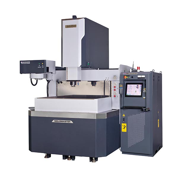
A645 EDM Machine
Die Sinking EDM with Moving Column Machine Structure- Features
- lift the machining tank.
- Moving Column Machine Structure
- The new Z-axis high-precision die.
- hoisting machine precision.
- New power supply and control system.
- 0.05% or less ultralow consumption circuit.
- HQSP gloss processing equipment (optional).
- Windows interface (optional).
Description
MOLDMASTER A-Series with high-precision, elevating work tank, fully automated technical support modern high-speed, unmanned production mold.Machine Specifications
| ITEM | UNIT | A645 | A540 | A430 |
|---|---|---|---|---|
| Work tank internal dimensions | W x D x H (mm) | 1175x760x500 | 900 x 620 x 400 | 750 x 530 x 350 |
| Max. workpiece dimensions | W x D x H (mm) | 1050x650x420 | 820 x 450 x 400 | 550 x 350 x 350 |
| Max. workpiece weight | kg | 1500 | 800 | 500 |
| Max. electrode weight | kg | 100 | 120 | 80 |
| X、Y, Z axis stroke | mm | 650×450×450 | 500 x 400 x 400 | 400 x 300 x 300 |
| Maximum moving speed | mm/min | X / Y / Z axis: 2000 | ||
| Table dimensions | W x D (mm) | 1050×650 | 820 x 450 | 550 x 350 |
| Distance between plate and table | mm | 350~800 | 250 ~ 650 | 300 ~ 600 |
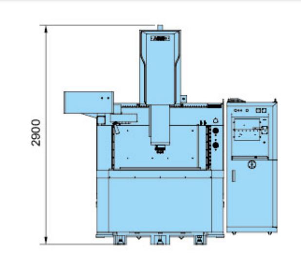
| Machine tool dimensions | W x D x H (mm) | 3400×1650×2750 | 1400 x 2400 x 2400 | 1250 x 2100 x 2150 |
| Volume of electric cabinet | W x D x H (mm) | 650 x 1080 x 1750 | ||
| Machine tool weight | kg | 4500 | 3065 | 2345 |
| Weight of electric cabinet | kg | 365kg(35A) / 390kg(50A) / 420kg(70A) / 470kg(105A) | ||
| Available power supplies | type | 35A(4KVA) / 50A(5.5KVA) / 70A(8KVA) / 105A(12KVA) | ||
| Dielectric reservoir capacity | L | 1000 | 800 | 600 |
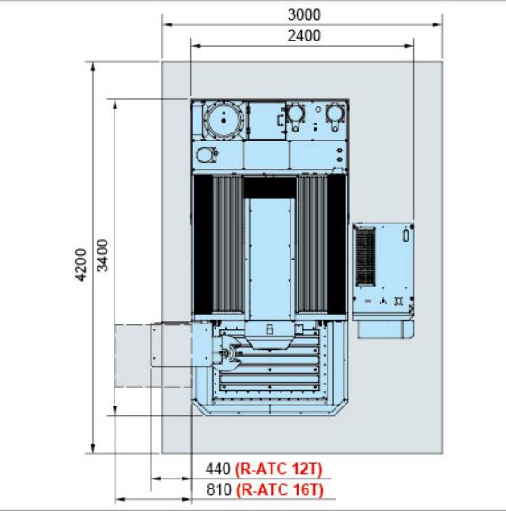
| Layout (AxB) (CxD) | mm | (3000×4200)(2400×3400) | (2650 x 3200) (2050 x 2400) | (2500 x 3000) (2170 x 2300) |
| Setting unit increments | μm | 1 | 1 | 1 |
| Optical scale resolutiion | μm | 1 | 1 | 1 |
- The work tank intimal dimensions means the applicable range on the table.
- Layout: A x B: (Machine + Reserve Space), C x D: (Machine)
- Specifications are subject to change without prior notice due to continual research and development.
- Standard Accessories:Fire extinguisher x 1 set, Electrode chuck x 1 set, Linear scale x 1 set, Tools box x 1 set、Flush magnetic base x 1 set, Filter x 2 pcs, Work lamp x 1 pc, Cooler x 1 set.
Optional equipment
| ITEM | UNIT | A645+ | A540+ | A430+ | |
|---|---|---|---|---|---|
| Auto Tooling System | 3R (MACRO), EROWA (ITS) | ||||
| Linear magazine* | Electrode No. | pcs | 4 / 5 / 6 | 4 / 5 | 4 |
| Max. Weight of electrode | kg | 5 | |||
| Max. Total weight of electrode | kg | 15(Geometric symmetry) | |||
| Diameter / Length | mm | 65 / 120 | |||
| Rotary magazine* | Electrode No. | pcs | 12 / 16 / 20 | ||
| Max. Weight of electrode | kg | 4 | |||
| Diameter / Length | mm | 65 / 120 | |||
| C-axis | Structure | Built-in type | |||
| Resolution | deg | 0.001 | |||
| Rotation | rpm | MOLDMASTER(0~14),3R (0~14), EROWA (0~14) | |||
| Max. Weight of electrode | kg | 25 | |||
| Max. electrode moment of inertia | kgcm2 | 75 | |||
| Dielectric-fluid injection/suction select | 4 / 1 | ||||
| Programmable flushing nozzle | O | ||||
| Dielectric-fluid cooler unit | O | ||||
| Voltage regulator unit (AVR)** | O | ||||
| System interface | DOS / WINDOWS (Touch panel) | ||||
| Graphite machining circuit (MD9) | O | ||||
| Large area machining circuit (MD8) | O | ||||
| Cemented carbide machining circuit (MD7) | O | ||||
| Micro-finish / Mirror polish machining circuit (MD4/6) | O | ||||
| Super-low wear circuit (MD3) | O | ||||
| High quality super polishing system (HQSP)*** | A645S+ | A540S+ | A430S+ | ||
- Linear and Rotary magazine must use air chuck (3R, EROWA).
- When variation of the AC power source is +15% over or -10%under, we recommend using AVR to improve stability.
- The relationship between machining area and surface roughness of HQSP is: 50Ø (Ra 0.15μm),400cm² (Ra 0.25μm).
Positioning Functions
| NA:Not available O:Available | |||
| Positioning Functions | C21-B | C21-A | Windows |
|---|---|---|---|
| Error Alignment | O | O | O |
| Millimeter / Inch Unit Conversion | O | O | O |
| Multiple Work Coordinates | O | O | O |
| Inner / Outer Measurements | O | O | O |
| Edge, Hole/Groove, Plate/Column Center Measurements | O | O | O |
| Reference Ball, Electrode Offset Compensation | O | O | O |
| Electric Discharge Position (EDP) | O | O | O |
| Quick Stop | O | O | O |
| Manual ATC | O | O | O |
| Multi-jog Simultaneously Moving | O | O | O |
Machining Cycles Functions
| NA:Not available O:Available | ||||
| Machining Cycles Functions | C21-B | C21-A | Windows | |
|---|---|---|---|---|
| Plunge Machining | (G111) | O | O | O |
| Expand machining | (G121) | O | O | O |
| Half Barrel Machining | (G123) | O | O | O |
| Orbital Machining | (G131) | O | O | O |
| Spiral Plunge Machining | (G133) | O | O | O |
| Pyramid Machining | (G135) | O | O | O |
| ISO-GAP Machining | (G153) | O | O | O |
| Multi-angle Machining | (G161) | O | O | O |
| CLW/CCLW Helical Machining | (G171) | NA | O | O |
| Vector Loran Machining | (G181) | O | O | O |
| Line/Grid Position | (G200) | O | O | O |
| Arc/Circle Position | (G210) | O | O | O |
| Contour Return | (G400) | O | O | O |
| Reference Plane Return | (G401) | O | O | O |
| Fast Feed for Positioning | (G00) | O | O | O |
| 2D Contour Machining | (G01, G02, G03) | O | O | O |
| 3D Contour Machining | (G01, G02, G03) | O | O | O |
| C Axis Indexing | (G00 + C) | O | O | O |
| Trans. Machining | (G01 + C) | O | O | O |
| Arc Trajectory Machining | (G02 / G03 + C) | O | O | O |
| Dwell | (G04) | O | O | O |
| Work Plane Selection | (G17, G18, G19) | O | O | O |
| Reference Point Return | (G28, G29) | O | O | O |
| Work Coordinate System | (G54 ~ G61) | O | O | O |
| Work Zero Setting | (G92) | O | O | O |
| Multi-point Machining | O | O | O | |
| Electrode Compensation | (H Code) | O | O | O |
| Miscellaneous Function | (M Cdde) | O | O | O |
| Polishing Time Control | (Q Code) | O | O | O |