Products
- Home
- Products
- Die Sinking EDM
- CNC EDM S SERIES
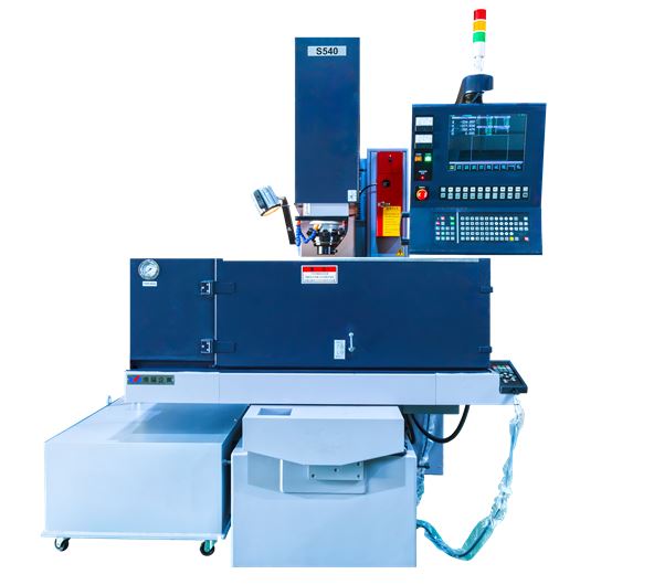
- S540 EDM Machine
CNC EDM S SERIES
S540 EDM Machine
C-type EDM machine- Features
- Newly designed high precision head (Z-axis)
- New Power Supply & Control System
- 0.05% or less ultralow consumption circuit
- HQSP The High Quality Super Polishing Equipment (optional)
- Windows interface (optional)
Description
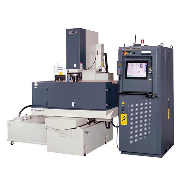
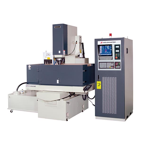
Reliability, efficiency, and performance are qualities that dictate the design of Moldmaster EDM. Discover the S540 EDM machine from Yawjet & Moldmaster, the largest C-frame model with strong spindle rigidity. This best-selling EDM machine offers advanced technology and superior precision, ideal for various industrial applications.Machine Specifications
| ITEM | UNIT | S540 | S430 | S430A | S430C | S320C |
|---|---|---|---|---|---|---|
| Work tank internal dimensions | W x D x H (mm) | 1300 x 800 x 380 | 1100 x 620 x 280 | 1100 x 620 x 280 | 1100 x 620 x 280 | 900 x 500 x 270 |
| Max. workpiece dimensions | W x D x H (mm) | 1045 x 700 x 330 | 850 x 500 x 230 | 850 x 500 x 230 | 850 x 500 x 230 | 670 x 350 x 220 |
| Max. workpiece weight | kg | 600 | 400 | 400 | 400 | 300 |
| Max. electrode weight | kg | 120 | 100 | 100 | 100 | 100 |
| X/Y/Z axes stroke | mm | 500 x 400 x 400 | 400 x 300 x 350 | 400 x 300 x 350 | 400 x 300 x 350 | 300 x 200 x 300 |
| Max. moving speed | mm/min | X / Y axis:1000;Z axis:2000 | ||||
| Table dimensions | W x D (mm) | 900 x 550 | 800 x 450 | 800 x 450 | 800 x 450 | 600 x 300 |
| Distance between plate and table | mm | 230 ~ 630 | 250 ~ 600 | 250 ~ 600 | 250 ~ 600 | 160 ~ 460 |
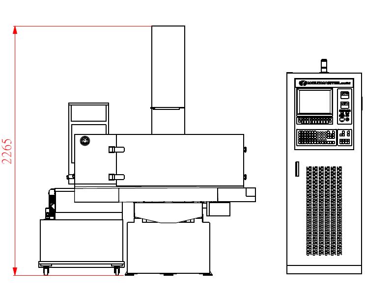
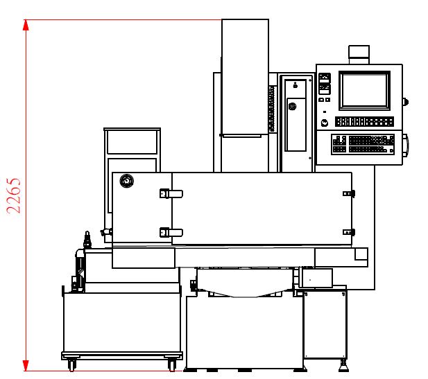
| Machine tool dimensions | W x D x H (mm) | 1700 x 1600 x 2250 | 1420 x 1350 x 2100 | 1800 x 1900 x 2200 | 1470x1370x2060 | 1400 x 1320 x 2100 |
| Volume of electric cabinet | W x D x H (mm) | 650 x 1080 x 1750 | - | 650 x 1080 x 1750 | ||
| Machine tool weight | kg | 2130 | 1680 | 2240 | 1825 | 1245 |
| Weight of electric cabinet | kg |
365kg(35A) / 390kg(50A) / 420kg(70A) / 470kg(105A) |
- | 365kg(35A) / 390kg(50A) / 420kg(70A) | ||
| Available power supplies | type |
50A(5.5KVA) / 70A(8KVA) / 105A(12KVA) |
35A(4KVA) / 50A(5.5KVA) / 70A(8KVA) | |||
| Dielectric reservoir capacity | l | 500 | 400 | 400 | 400 | 200 |
|
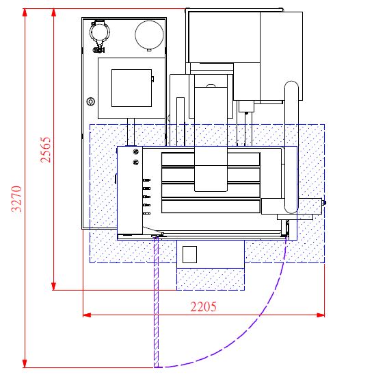
Layout(AXB)(CXD) |
mm | (3850X2960)(3250X2165) | (3450X3440)(2530X2230) | (2950X3250)(2350X2500) | (3120X2465)(2520X1665) | (2730X2225)(2130X1425) |
| Setting unit increments | μm | 1 | 1 | 1 | 1 | 1 |
| Optical scale resolutiion | μm | 1 | 1 | 1 | 1 | 1 |
- The work tank internal dimensions means the applicable range on the table.
- Leave about 60cm between the machine and the wall or other machine.
- Layout Dimensions: A x B means (machine + reserved space), C x D means (machine).
- Specifications are subject to change without prior notice due to continual research and development.
- Standard Accessories: Fire extinguisher x 1 set, Electrode chuck x 1 set, Linear scale x 1 set, Tools box x 1 set、Flush magnetic base x 1 set,
- Filter x 2 pcs, Work lamp x 1 pc.
Optional equipment
| ITEM | UNIT | S540 | S430 | S430A | S430C | A320C | |
|---|---|---|---|---|---|---|---|
| Auto Tooling System | 3R (MACRO), EROWA (ITS) | ||||||
| Linear magazine* | Electrode No. | pcs | 6 | 4 | 3 | ||
| Max. Weight of electrode | kg | 5 | |||||
| Max. Total weight of electrode | kg | 15(Geometric symmetry) | |||||
| Diameter/Iength | mm | 65/120 | |||||
| Rotary Magazine* | Electrode No. | 12 / 16 / 20 | NA | ||||
| Max. Weight of electrode | kg | 4 | NA | ||||
| Diameter/Iength | mm | 65 / 120 | NA | ||||
| C-axis | Structure | Built-in type | |||||
| Resolution | deg | 0.001 | |||||
| Rotation | rpm | MOLDMASTER(0~14),3R (0~14), EROWA (0~14) | |||||
| Max. Electrode carrying weight | kg | 25 | |||||
| Max. Electrode moment of inertia | kgcm2 | 75 | |||||
| Dielectric-fluid injection / Suction select | 4/1 | ||||||
| Programmable flushing nozzle | O | ||||||
| Dielectric-fluid cooler unit | O | ||||||
| Voltage regulator unit (AVR)** | O | ||||||
| Automatic back flushing system | O | ||||||
| System interface | DOS/WINDOWS(Touch panel) | ||||||
| Graphite machining circuit (MD9) | O | ||||||
| Large area machining circuit (MD8) | O | ||||||
| Cemented carbide machining circuit (MD7) | O | ||||||
| Micro-finish / Mirror polish machining circuit (MD4/6) | O | ||||||
| Super-low wear circuit (MD3) | O | ||||||
| High quality super polishing system (HQSP***) | S540S | S430S | S430AS | NA | NA | ||
- Linear and Rotary magazine must use air chuck (3R, EROWA).
- When variation of the AC power source is +15% over or -10% under, we recommend using AVR to improve stability.
- The relationship between machining area and surface roughness of HQSP is: 50Ø (Ra 0.15µm), 400cm² (Ra 0.25µm).
Positioning Functions
| NA:Not available O:Available | |||||||
| Control System | Dos/Windows | ||||||
|---|---|---|---|---|---|---|---|
| Positioning Functions | C15-B | C15-AB | C15-A | C21-B | C21-A | Windows | |
| Error Alignment | O | O | O | O | O | O | |
| Millimeter / Inch Unit Conversion | O | O | O | O | O | O | |
| Multiple Work Coordinates | O | O | O | O | O | O | |
| Inner / Outer Measurements | O | O | O | O | O | O | |
| Edge, Hole/Groove, Plate/Column Center Measurements | O | O | O | O | O | O | |
| Reference Ball, Electrode Offset Compensation | O | O | O | O | O | O | |
| Electric Discharge Position (EDP) | O | O | O | O | O | O | |
| Quick Stop | O | O | O | O | O | O | |
| Manual ATC | NA | O | O | O | O | O | |
| Multi-jog Simultaneously Moving | O | O | O | O | O | O | |
Machining Cycles Functions
| NA:Not available O:Available | |||||||
| Control System | Dos/Windows | ||||||
|---|---|---|---|---|---|---|---|
| Machining Cycles Functions | C15-B | C15-AB | C15-A | C21-B | C21-A | Windows | |
| Plunge Machining | (G111) | O | O | O | O | O | O |
| Expand Machining | (G121) | O | O | O | O | O | O |
| Half Barrel Machining | (G123) | NA | NA | O | O | O | O |
| Orbital Machining | (G131) | NA | O | O | O | O | O |
| Spiral Plunge Machining | (G133) | O | O | O | O | O | O |
| Pyramid Machining | (G135) | NA | O | O | O | O | O |
| ISO-GAP Machining | (G153) | NA | NA | O | O | O | O |
| Multi-angle Machining | (G161) | NA | O | O | O | O | O |
| CLW/CCLW Helical Machining | (G171) | NA | NA | NA | NA | O | O |
| Vector Loran Machining | (G181) | O | O | O | O | O | O |
| Line/Grid Position | (G200) | O | O | O | O | O | O |
| Arc/Circle Position | (G210) | O | O | O | O | O | O |
| Contour Return | (G400) | O | O | O | O | O | O |
| Reference Plane Return | (G401) | O | O | O | O | O | O |
| Fast Feed for Positioning | (G00) | O | O | O | O | O | O |
| 2D Contour Machining | (G01, G02, G03) | O | O | O | O | O | O |
| 3D Contour Machining | (G01, G02, G03) | O | O | O | O | O | O |
| C Axis Indexing | (G00+C) | NA | NA | NA | O | O | O |
| Trans. Machining | (G01+C) | NA | NA | NA | O | O | O |
| Arc Trajectory Machining | (G02 / G03+C) | NA | NA | NA | O | O | O |
| Dwell | (G04) | O | O | O | O | O | O |
| Work Plane Selection | (G17, G18, G19) | Only G17 | O | O | O | O | O |
| Reference Point Return | (G28, G29) | O | O | O | O | O | O |
| Work Coordinate System | (G54 ~ G61) | O | O | O | O | O | O |
| Work Zero Setting | (G92) | O | O | O | O | O | O |
| Multi-point Machining | O | O | O | O | O | O | |
| Electrode Compensation | (H Code) | O | O | O | O | O | O |
| Miscellaneous Function | (M Code) | O | O | O | O | O | O |
| Polishing Time Control | (Q Code) | O | O | O | O | O | O |