Products
- Home
- Products
- Die Sinking EDM
- CNC EDM M SERIES
- M2170-2H EDM Machine
CNC EDM M SERIES
M2170-2H EDM Machine
Ram-type Structure EDM machine- Features
- Machine Tool - Finite Element Structure Analysis
- Ram-type Machine Structure
- New Power Supply & Control System
- 0.05% or less ultralow consumption circuit
- HQSP The High Quality Super Polishing Equipment (optional)
- Windows interface (optional)
Description
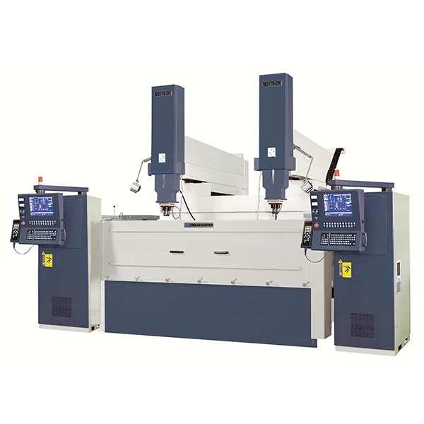
Each aspect of machine must be engineered to be extremely durable and exactingly precise. Discover the M2170-2H dual-spindle EDM machine from Yawjet & Moldmaster, the largest EDM machine designed for precision automotive mold machining. This advanced machine features two spindle heads that can operate simultaneously, significantly improving machining efficiency and productivity for large automotive molds.Machine Specifications
| ITEM | UNIT | M2170-2H | M1670 | M1470 | M1270 |
|---|---|---|---|---|---|
| Work tank internal dimensions | W x D x H (mm) | 2890X1700X800 | 2550X1500X670 | 2400X1500X670 | 2250x1500x670 |
| Max. workpiece dimensions | W x D x H (mm) | 2600X1200X700 | 2300X1000X600 | 2200X1000X600 | 2000x1000x600 |
| Max. workpiece weight | kg | 5000 | 4000 | 4000 | 4000 |
| Max. electrode weight | kg | 300 | 300 | 300 | 300 |
| X、Y、Z axis stroke | mm | 1050X700X500/600* | 1600X700X500/600* | 1400X700X500/600* | 1200x700x500/600* |
| Maximum moving speed | mm/min | X,Y axis:1000 Z axis:2000 | |||
| Table dimensions | W x D (mm) | 2250X1100 | 1800X960 | 1800X960 | 1800x960 |
| Distance between plate and table | mm | 530~1030/1130* | 550~1050/1150* | 550~1050/1150* | 550~1050/1150* |
| Machine tool dimensions | W x D x H (mm) | 5500X4600X3750 | 3200X3150X3350/3450* | 3050X3150X3350/3450* | 2900x3150x3350/3450* |
| Volume of electric cabinet | W x D x H (mm) | 650X1080X1750 | |||
| Machine tool weight | kg | 15000 | 11000 | 10950 | 10750 |
| Weight of electric cabinet | kg | 390kg(50A) / 420kg(70A) / 470kg(105A) / 570kg(140A) / 620kg(175A) / 670kg(200A) | |||
| Available power supplies | type | 50A(5.5KVA) / 70A(8KVA) / 105A(12KVA) / 140A(16KVA) / 175A(20KVA) / 200A(24KVA)} | |||
| Dielectric reservoir capacity | L | 4600 | 3200 | 3000 | 2800 |
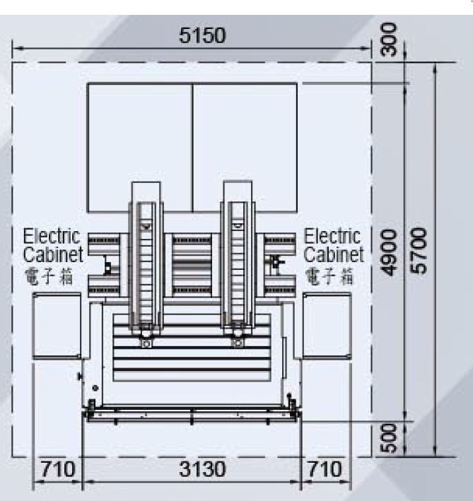
| Layout(AXB)(CXD) | mm |
(5150x5700)(4850x4900) |
(4710x5500)(4110x4700 | (4710x5500)(4110x4700 | (4710x5500)(4110x4700 |
| Setting unit increments | μm | 1 | 1 | 1 | 1 |
| Optical scale resolution | μm | 1 | 1 | 1 | 1 |
- The work tank internal dimensions means the applicable range on the table.
- Leave about 60cm between the machine and the wall or other machine.
- Specifications are subject to change without prior notice due to continual research and development.
- * is optional.
- Standard Accessories: Fire extinguisher x 1 set, Electrode chuck x 1 set, Linear scale x 1 set, Tools box x 1 set、Flush magnetic base x 1 set, Filter x 2 pcs, Work lamp x 1 pc, Cooler x 1 set.
Optional equipment
| ITEM | UNIT | M2170-2H | M1670 | M1470 | M1270 | M1060 | M860 | M645 | M540+ | |
|---|---|---|---|---|---|---|---|---|---|---|
| Auto Tooling System | 3R (MACRO), EROWA (ITS) | |||||||||
| Linear magazine* | Electrode No. | pcs | 4 / 6 | |||||||
| Max. Weight of Electrode | kg | 5 | ||||||||
| Max. Total weight of electrode | kg | 15(Geometric symmetry) | ||||||||
| Diameter/Iength | mm | 65 / 120 | ||||||||
|
Rotary magazine* |
Electrode No. | pcs | 12 / 16 / 20 | |||||||
| Max. Weight of Electrode | kg | 4 | ||||||||
| Diameter/Iength | mm | 65 / 120 | ||||||||
| C-axis | Structure | Built-in type | ||||||||
| Resolution | deg | 0.001 | ||||||||
| Rotation | rpm | MOLDMASTER(0~14),3R (0~14), EROWA (0~14) | ||||||||
| Max. Eiectrode carrying weight | kg | 25 | ||||||||
| Max. Electrode moment of inertia | kgcm2 | 75 | ||||||||
| Dielectric-fluid Injection/Suction Select | 6 / 1 | |||||||||
| Programmable Flushing Nozzle | O | |||||||||
| Dielectric-fluid Cooler Unit | Std. | |||||||||
| Voltage Regulator Unit (AVR)** | O | |||||||||
| Automatic Back Flushing System | O | |||||||||
| System Interface | DOS / WINDOWS (Touch panel) | |||||||||
| Graphite Machining Circuit (MD9) | O | |||||||||
| Large area Machining Circuit (MD8) | O | |||||||||
| Cemented Carbide Machining Circuit (MD7) | O | |||||||||
| Micro-finish / Mirror Polish Machining Circuit (MD4/6) | O | |||||||||
| Super-low Wear Circuit (MD3) | O | |||||||||
| High Quality Super Polishing System (HQSP***) | NA | NA | NA | M1270S | M1060S | M860S | M645S | M540S+ | ||
- Linear and Rotary magazine must use air chuck (3R, EROWA).
- When variation of the AC power source is +15% over or -10% under, we recommend using AVR to improve stability.
- The relationship between machining area and surface roughness of HQSP is: 50Ø (Ra 0.15µm), 400cm² (Ra 0.25µm).
Positioning Function
| NA:Not available O:Available | ||||
| Control System | Dos/Windows | |||
|---|---|---|---|---|
| Positioning Function | C15-A | C21-B | C21-A | Windows |
| Error Alignment | O | O | O | O |
| Millimeter / Inch Unit Conversion | O | O | O | O |
| Multiple Work Coordinates | O | O | O | O |
| Inner / Outer Measurements | O | O | O | O |
| Edge, Hole/Groove, Plate/Column Center Measurements | O | O | O | O |
| Reference Ball, Electrode Offset Compensation | O | O | O | O |
| Electric Discharge Position (EDP) | O | O | O | O |
| Quick Stop | O | O | O | O |
| Manual ATC | O | O | O | O |
| Multi-jog Simultaneously Moving | O | O | O | O |
Machining Cycles Functions
| NA:Not available O:Available | |||||
| Control System | Dos/Windows | ||||
|---|---|---|---|---|---|
| Machining Cycles Functions | C15-A | C21-B | C21-A | Windows | |
| Plunge Machining | (G111) | O | O | O | O |
| Expand machining | (G121) | O | O | O | O |
| Half Barrel Machining | (G123) | O | O | O | O |
| Orbital Machining | (G131) | O | O | O | O |
| Spiral Plunge Machining | (G133) | O | O | O | O |
| Pyramid Machining | (G135) | O | O | O | O |
| ISO-GAP Machining | (G153) | O | O | O | O |
| Multi-angle Machining | (G161) | O | O | O | O |
| CLW/CCLW Helical Machining | (G171) | NA | NA | O | O |
| Vector Loran Machining | (G181) | O | O | O | O |
| Line/Grid Position | (G200) | O | O | O | O |
| Arc/Circle Position | (G210) | O | O | O | O |
| Contour Return | (G400) | O | O | O | O |
| Reference Plane Return | (G401) | O | O | O | O |
| Fast Feed for Positioning | (G00) | O | O | O | O |
| 2D Contour Machining | (G01, G02, G03) | O | O | O | O |
| 3D Contour Machining | (G01, G02, G03) | O | O | O | O |
| C Axis Indexing | (G00 + C) | NA | O | O | O |
| Trans. Machining | (G01 + C) | NA | O | O | O |
| Arc Trajectory Machining | (G02 / G03 + C) | NA | O | O | O |
| Dwell | (G04) | O | O | O | O |
| Work Plane Selection | (G17, G18, G19) | O | O | O | O |
| Reference Point Return | (G28, G29) | O | O | O | O |
| Work Coordinate System | (G54 ~ G61) | O | O | O | O |
| Work Zero Setting | (G92) | O | O | O | O |
| Multi-point Machining | O | O | O | O | |
| Electrode Compensation | (H Code) | O | O | O | O |
| Miscellaneous Function | (M Code) | O | O | O | O |
| Polishing Time Control | (Q Code) | O | O | O | O |