Products
- Home
- Products
- Die Sinking EDM
- ZNC EDM Y SERIES
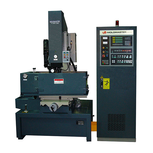
- Y320C-ZNC/MP52 EDM machine
ZNC EDM Y SERIES
Y320C-ZNC/MP52 EDM machine
ZNC EDM machine- Features
- 5μlinear scale feedback
- More than 500 ECODE data
- 7 steps automatic fine machining
- High C/P value
Description
Yawjet’s Y320C-ZNC traditional EDM machine is the most compact model in its series, with the oil tank located beneath the machine to save space. Designed for high-precision and high-efficiency EDM processing, it is ideal for performing complex and fine industrial machining tasks, delivering stable and reliable performance to meet stringent manufacturing standards.Machine Specifications
| ITEM | UNIT | Y540-ZNC MP52 |
Y430-ZNC MP52 |
Y430A**-ZNC MP52 |
Y320C*-ZNC MP52 |
Y320A**-ZNC MP52 |
|---|---|---|---|---|---|---|
| Work tank internal dimensions | W x D x H (mm) | 1200 x 700 x 430 | 1000 x 600 x 400 | 1000 x 600 x 400 | 880x 500 x 320 | 880 x 500 x 320 |
| Max. workpiece dimensions | W x D x H (mm) | 960 x 560 x 380 | 800 x 500 x 350 | 800 x 500 x 350 | 650 x 350 x 270 | 650 x 350 x 270 |
| Max. workpiece weight | kg | 1000 | 600 | 600 | 400 | 400 |
| Max. electrode weight | kg | 120 | 100 | 100 | 100 | 100 |
| X、Y、Z axis stroke | mm | 500 x 400 x 250 | 400 x 300 x 200 | 400 x 300 x 200 | 300 x 225 x 200 | 300 x 225 x 200 |
| Z back slide travel | mm | 200 | 200 | 200 | 200 | 200 |
| Table dimensions | W x D (mm) | 900 x 650 | 800 x 450 | 800 x 450 | 600 x 300 | 600 x 300 |
| Distance between plate and table | mm | 350 ~ 800 | 290 ~ 690 | 290 ~ 690 | 210 ~ 610 | 210 ~ 610 |
| Machine tool dimensions | W x D x H (mm) | 1660 x 1650x2270 | 1370 x 1410x2120 | 1790 x 1880x2220 | 1400 x 1320x2100 | 1790 x 1610x2100 |
| Volume of electric cabinet | W x D x H (mm) | 650x1080x1750 | ||||
| Machine tool weight | kg | 2070 | 1665 | 2050 | 1205 | 1450 |
| Weight of electric cabinet | kg | 360kg(30A) / 385kg(50A) / 415kg(75A) / 465kg(100A) | ||||
| Available power supplies | type | 30A(4KVA) / 50A(5.5KVA) / 75A(8KVA) / 100A(12KVA) | ||||
| Dielectric reservoir capacity | L | 500 | 400 | 400 | 200 | 200 |
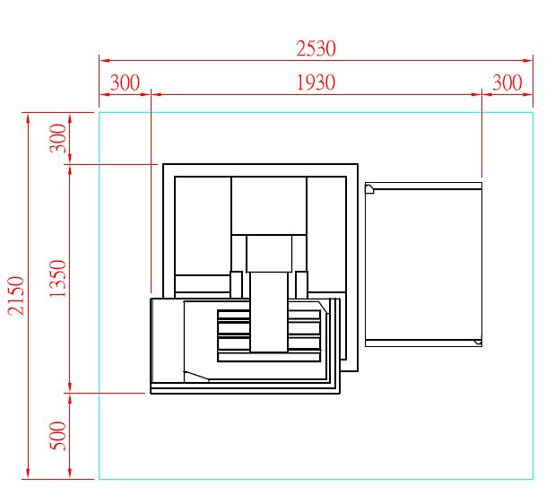
| Layout(AXB)(CXD) | mm | (3850x2750)(3250x1945) | (3450x2650)(2850x1850) | (2650x2600)(2050x1800) | (2530x2150)(1930x1350) | (2150x2150)(1550x1350) |
| Setting unit increments | μm | 5 | 5 | 5 | 5 | 5 |
| Optical scale resolution | μm | 5 | 5 | 5 | 5 | 5 |
- *C means Compact space design-2 pcs.
- **A means Compact space design-all in one.
- Layout: A x B: (Machine + Reserve Space), C x D: (Machine).
- The work tank internal dimensions means the applicable range on the table.
- Specifications are subject to change without prior notice due to continual research and development.
- STANDARD ACCESSORIES:Worklamp, Fire extinguisher, Flush plate, Tool box, Electrode holder.
Optional equipment
| ITEM | TNC | ZNC |
|---|---|---|
| Standard discharge circuit and control system |
|
|
| Optional discharge circuit and control system |
|
|
- When variation of the AC power source is +15% over or -10% under, we recommend using AVR to improve stability.